|
1.初始磁导率μi
初始磁导率是磁性材料的磁导率(B/H)在磁化曲线始端的极限值,即
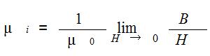
式中μ0为真空磁导率(4π×10-7 H/m)
H 为磁场强度(A/M)
B 为磁通密度(T) |
1.Initial permeabilityμi
The initial permeabilityμi is the limit value at the initial magnetization curve’s origin point and is given by the following formula
Where
μ0:Permeability of absolute vacuum(4π×10-7 H/m)
H: Magnetic field strength(A/M)
B:Magnetic flux density(T) |
|
2. 有效磁导率μe
对于磁路截面不均匀的闭路磁芯或非故意在磁路中开气隙(通常所说的平面配对)的磁芯及需要在磁路中开气隙的磁芯,可以用有效磁导率来表征磁芯的性能。
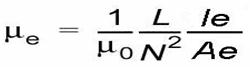
式中 L为装有磁芯的线圈的电感量(H)
N为线圈匝数
Le为有效磁路长度(m)
Ae 为有效截面积 (m2)
|
2.Effective permeability μe
The cora forming a closed circuit of uneven corss-sectional area ofmagnetic path or cores with gaps in the magnetic circuit without intention(that is general plane cores in pairs)and cores to be needed to make gap,the performance of these core can be characterized by effective permeability.
Where
L:self-inductance of cre with coil(H)
N:number of turns
Le:effective magnetic path length(m)
Ae:effective cross-sectional area(m2) |
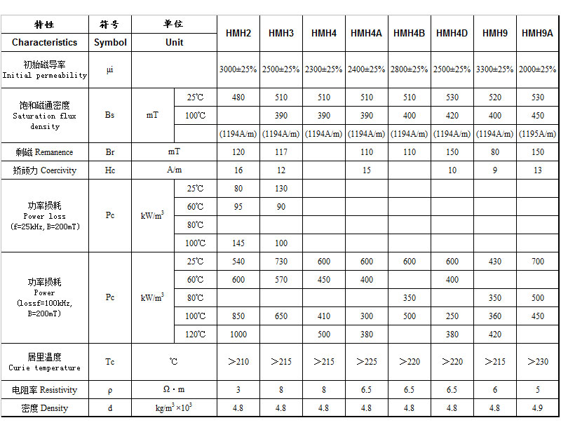
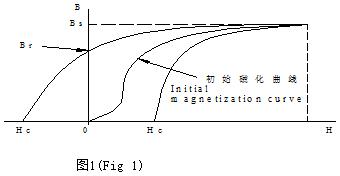
3.饱和磁通密度Bs ( T )
磁化到饱和状态的磁通密度。见图1。
 |
3.Saturation magnetic flux density,Bs(T)
The magnetic fiux density at a magnetic field where H is up to an approximate saturation magnetic field value
|
4. 剩余磁通密度(剩磁)Br ( T )
从饱和状态去除磁场后,剩余的磁通密度。(见图1) |
4.Residual magnetic flux density,Br(T)
The value of flux density retained by the core when the magnetic field is reduced the state of
the effective saturation magnetic fiux density
to zero.(Fig 1) |
5.矫顽力Hc ( A / m )
从饱和状态去除磁场后,磁芯继续被反向磁场磁化,直至磁通密度减为零,此时的磁场强度称为矫顽力。见图1。 |
5.Coercivity, HC(A/M)
The value of magnetic field strength whereby the fiux density becomes zero under the intensification,in the opposite direction,of the magnetic field. (Fig.1) |
6. 损耗因数tanδ
损耗因数是磁滞损耗、涡流损耗和剩余损耗三者之和
tanδ= tanδh + tanδe + tanδr
式中 tanδh为磁滞损耗因数
tanδe为涡流损耗因数
tanδr为剩余损耗因数 |
6.Loss factor,tanδ
This is the sum of the hysteresis loss factor ,eddy current loss factor and residual loss factor
tanδ= tanδh+ tanδe+ tanδr
Where tanδh is the hysteresis loss factor
tanδe is the eddy current loss factor
tanδr is the residual loss factor |
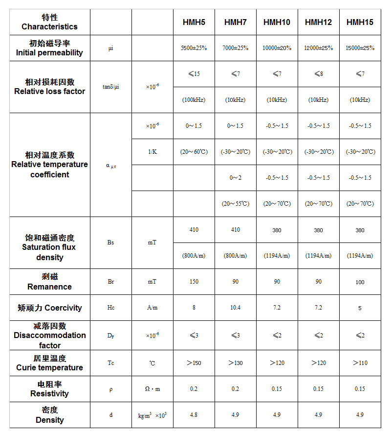
7. 相对损耗因数tanδ/μ 相对损耗因数是损耗因数与磁导率之比:
tanδ/ μi (适用于材料)
tanδ/ μe (适用于磁路中含有气隙的磁芯) |
7.Relative lossfactor,tanδ/μ
This is the ratio of loss factor to permeability
tanδ/ μi (for materials)
tanδ/ μe(for cores with gaps in the magnetic circuit) |
8. 品质因数Q 品质因数为损耗因数的倒数:
Q = 1/ tanδ |
8.Quality factor,Q
This is the reciprocal of the loss factor
and is given by
Q = 1/ tanδ |
|
9. 温度系数αμ (1/K )
温度系数为温度在T1和T2范围内变化时,每变化1K相应的磁导率的相对变化量: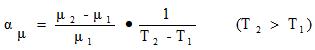
式中 μ1为温度为T1时的磁导率
μ2为温度为T2时的磁导率 |
9.Temperature coefficient,αμ (1/K )
This is the fractional difference of permeability
per 1K in a temperature range of from T1 to T2
Where μ1:permeability at temperature T1
μ2:permeability at temperature T2
|
10. 相对温度系数α μ r ( 1/K )
温度系数和磁导率之比,即
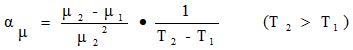 |
10.Relative temperature coefficent,αμr ( 1/K )
This is the temperature coefficent per unit
permeability and is given by the following
equation:
|
11. 居里温度Tc (℃ )
在该温度下材料由铁磁性(或亚铁磁性)转变成顺磁性(见图2)
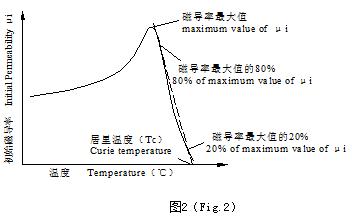 |
11.Curie temperature,Tc
It is the critical temperature level at which the
ferromagnetic state of the material changes to
paramagnetic state.(Fig.2)
|
|
12. 减落因数DF
在恒温条件下,完全退磁的磁芯的磁导率随时间的衰减变化,即
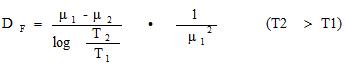
式中 μ1 为退磁后t1时刻的磁导率
μ2为退磁后t2时刻的磁导率 |
12.Disaccom modation factor,DF
This is the factor representing the variation of permeability through time
after a complete demagnetization of the core at a
constant temperature.
Where
μ1:permeability t1 time after complete demagnetization.
μ2:permeability t2 timeafter complete demagnetization.
|
13. 电阻率ρ (Ω/m)
单位截面积和单位长度的磁性材料的电阻。 |
13.Electrical resistivity,ρ (Ω/m)
This is the electrical resistance per unit length
and |
|
14. 密度d (kg/m3 )
单位体积磁性材料的重量,即
d = W/V
式中 W 为磁芯的重量 (kg )
V 为磁芯的体积 ( m3 ) |
14.Density, d (kg/m3 )
This is weight per unit volume of a magnetic core
as expressed below:
d = W/V
Where W:weight of magnetic boby(kg)
V:volume of magnetic boby( m3 ) |
|
15. 功率损耗Pc (kW/ m3 )
磁芯在高磁通密度下的单位体积损耗。该磁通密度可表示为
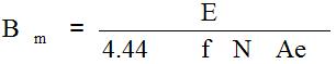 式中 E 为施加在线圈上的电压有效值 (V) 式中 E 为施加在线圈上的电压有效值 (V)
Bm 为磁通密度的峰值 ( T )
f 为频率 ( Hz )
N为线圈匝数
Ae为有效截面积 ( m2 )
目前,功率损耗的常用测量方法包括乘积电压表法和波形记忆法。 |
15.Power loss pc (kW/ m3 )
Power loss denotes the loss by an electrical transformer
,such as a switching power supply,under a magnetization
condition featuring a high frequency and large
amplitude.Operating magnetic flux density is given
by the following equation.
Where
E:Voltage effective value applied to coil
BM:peak value of magnetic flux density
f:frequency(HZ)
N:number of coil turns
AE:effective cross-sectional area(m2)
At present,the usual ways to measure the power loss are Multi-voltmeter Method and Waveform Memory Method |
|
16. 电感因数AL ( nH / N 2 )
电感因数定义为具有一定形状和尺寸的磁芯上每一匝线圈产生的电感量,即
AL = L / N2
式中 L为装有磁芯的线圈的电感量 (H)
N为线圈匝数
电感因数一般以nH/N2(10-9H/N2)为单位 |
16.Inductance factor AL( nH / N 2 )
This is the inductance per ture of the coil wound around the ferrite cores
with definite shape and dimension.
AL=L/N2
Where
L:indductance of the coil with ferrite core
N:turns of the coil
The inductance factor is usually united by nH/N2(10-9H/N2) |